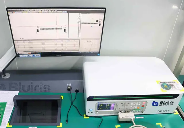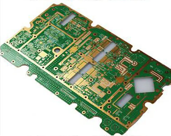
INE Technologies is a German semiconductor manufacturer listed on the DAX and one of the world's leading producers of automotive and power semiconductors. Automotive is the core business at about half of revenue, with power and sensor systems at around 29 %, green industrial power at 11 % and connected secure systems at 10 %. From May 2025 the company is consolidating into three divisions — Automotive, Power Systems and Edge — and has acquired Marvell's automotive Ethernet business and ams OSRAM's non-optical analog/mixed-signal sensor business, moving towards system-level supply for software-defined vehicles.
Its portfolio spans AURIX™ automotive MCUs, SiC/IGBT power modules, RASIC™ mmWave radar chips, automotive sensors, Ethernet and security ICs, and it serves global Tier-1s such as Bosch, Continental and ZTE before the OEMs. The 77/79 GHz radar chips are flagship parts, used in automatic emergency braking, adaptive cruise control, blind-spot monitoring and in-cabin vital-sign detection — safety-critical functions that make supply-chain requirements exceptionally strict.
The programme
In early 2026 an automotive radar project entered prototype validation. The brief was a board that leaves no room for trial and error:
- 10 layers, and not a conventional stack-up — FR4 Tg180 hybrid-laminated with Rogers RO3003
- ENIG surface finish
- BGA, QFN and 77 GHz antenna feed lines on the same board
- Sample lead time of two weeks, volume in three to four weeks
- Automotive microwave radar, a safety part where rework must never mask a defect
Supplier approval set the floor: IATF 16949 as the entry ticket, APQP/PPAP as standard practice, IPC-A-600/610 Class 3 as the acceptance baseline, and full traceability with a zero-defect culture as the real test.
Where the difficulty lies
RO3003 is a ceramic-filled PTFE-based high-frequency laminate with a dielectric constant of about 3.0 and very low loss, which is why it suits 77 GHz radar. But its coefficient of thermal expansion, curing behaviour, resin flow and stiffness differ fundamentally from FR4, so laminating the two into a single 10-layer board is like bonding two materials with opposite temperaments.
The barriers that decide the board:
- CTE mismatch — warpage and delamination. FR4 Tg180 expands and contracts differently from RO3003, so layers shrink at different rates during lamination, reflow and thermal cycling. The result is board warpage, interlayer delamination and reduced PTH reliability.
- A lamination window that has to satisfy two curing regimes. FR4 prepreg needs higher temperatures to cure fully, while the RO3003/PTFE system is more sensitive to high temperature, pressure and resin flow. Under-curing, excessive resin flow and uneven thickness are all live risks.
- Bonding film selection. Standard FR4 prepreg cannot bond Rogers high-frequency layers directly: it produces discontinuous Dk/Df and insufficient bond strength, which shows up as impedance deviation, higher loss and a greater risk of delamination.
- Impedance control across two dielectrics. RO3003 is Dk ≈ 3.00 against FR4's 4.2–4.5, so the effective Dk changes abruptly where a signal crosses between them and impedance moves in microstrip and stripline structures.
- Drilling, hole metallisation and registration. PTFE has different hole-wall roughness, desmear requirements and wettability from FR4, which raises the risk of poor adhesion, hole cracking and CAF formation; different expansion also shifts registration for blind and buried vias and fine-pitch BGA areas.
What engineering changed on the line
- A symmetrical stack-up. High-frequency cores, FR4 cores and bonding films are mirrored top to bottom and copper distribution is balanced, so post-lamination warpage stays low.
- Compatible bonding films. Instead of standard FR4 prepreg, low-loss bonding films or transition prepregs recommended by Rogers or validated in-house are used, keeping interlayer bond strength and avoiding a Dk jump at the interface.
- A customised lamination profile. FR4 Tg180's cure requirement is balanced against the stability of RO3003 with a stepped heating curve, vacuum lamination and controlled slow cooling under pressure, rather than a fast ramp and quench.
- High-frequency traces kept within one dielectric. RF and microwave traces on RO3003 stay in the same layer; routing that crosses from the Rogers area into FR4, or changes layer across the boundary, is avoided because it makes impedance and loss far harder to hold.
- Drilling and surface finish treated separately. Because RO3003 is PTFE-based, hole walls get special treatment such as plasma activation before metallisation, and drilling parameters are optimised apart from FR4 to keep hole-wall quality consistent.
Results
Samples were delivered in two weeks and every functional test passed first time, with impedance and insertion loss close to the centre of spec. The 10-layer hybrid boards showed zero delamination and zero out-of-tolerance warpage, and C-SAM and micro-sections all conformed. The first volume batch was completed in 3.5 weeks at a 99.6 % first-pass yield, with no reworked lots shipped. Board-level traceability ran throughout: material lot, lamination profile, equipment parameters and test data mapped one-to-one.
Customer feedback
The customer confirmed that prototype and volume orders for subsequent radar platforms will continue with HITECH CIRCUITS, and plans to bring more high-frequency hybrid projects into the cooperation. For a customer like INE, speed is the entry ticket and stability is the basis for a long-term partnership; this programme was judged on both.
What it shows
A radar board tests more than equipment age — it tests engineering judgment: the honesty to flag where a build will go wrong before quoting rather than after scrapping a lot, real high-frequency process experience rather than FR4 habits applied to PTFE, and project management that can break 48 hours into hourly milestones by process rather than by luck.
The operating base behind the work is ISO 9001 / ISO 14001 / ISO 45001 / IATF 16949 / ISO 13485, so speed never comes at the cost of stability. The process limits are on the capability page; the board families have their own pages for high-frequency and RF PCBs and multilayer boards; the industry context sits on the automotive and vehicles page. To start a similar programme, send the Gerber set, BOM and target date on the contact page.