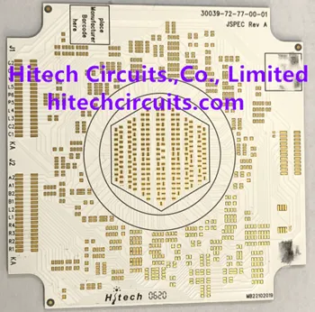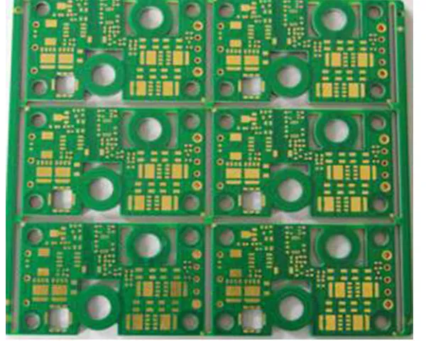
An aluminium or metal-core board carries the circuit on a thermally conductive dielectric bonded to a metal base. The heat path runs straight down through the base instead of sideways through the copper, which is why lighting, power and motor-drive designs use it: the board itself is the heat sink.
Why a metal base instead of FR-4
- Thermal path — heat spreads through the base under every hot component, so LED pads, MOSFETs and shunt resistors do not need a separate aluminium heat sink bolted underneath.
- Mechanical rigidity — a metal core resists bending at long and thin shapes where FR-4 would need stiffeners.
- Current capacity — copper from 18 µm to 240 µm carries the load of a driver or power stage without widening the layout.
- Dimensionally stable — warp and twist stay below 0.5 mm across the 5 × 5 mm to 1900 × 480 mm size range.
Constructions built here
Single-sided MCPCB with a punched or routed outline, double-sided and 2 to 4 layer metal-core boards, COB MCPCB for chip-on-board LED arrays, and copper-base boards where aluminium is not thermally conductive enough. Driver and control sections that need more density are built on FR-4 up to 38 layers and produced in the same order as the metal-core part.
Is a metal-core board the right choice?
A metal base earns its place when the heat covers an area and the board can be fastened to a metal housing: LED arrays, driver stages and motor-drive power sections. It is the wrong tool when the density sits in the routing rather than in the heat — a fine-pitch control board with one hot regulator belongs on FR-4 with a thermal via field, and only the area where the current lands needs the metal core.
The three bases differ by thermal headroom: standard aluminium covers most lighting work, a copper base board is used where aluminium cannot pull the heat out of a small footprint, and COB MCPCB where the die is bonded to the board instead of being reflowed as a package. Where the dielectric itself has to hold the voltage, a ceramic substrate takes over from a thicker metal core.
What the process holds
Minimum trace width and spacing are 0.1 mm with hole position tolerance of ±0.075 mm, so the LED pitch and the connection to the rest of the fixture are fixed before panelisation. Drilled holes start at 0.2 mm, punched holes at 1.0 mm, and square slots from 0.8 × 0.8 mm are punched in the same pass as the outline. Hole wall copper runs 18–40 µm, silk print and component marking hold ±0.075 mm, and the smallest component mark is 0.15 mm.
Where a metal-core board fails in service
Most field returns on these boards trace back to four points, and each one is settled on the drawing rather than on the line:
- Dielectric breakdown at the pad edge — the field concentrates where a pad ends, so pad geometry and dielectric are chosen together with the drive current, not with the copper weight.
- Solder mask cracking beside a V-cut — separating the panel stresses the mask next to the groove, so the break line is kept clear of the pad edge.
- Warp after the housing clamps the panel — a panel that leaves the press flat can still bow in the fixture, so warp is held below 0.5 mm and the outline is routed or punched to the drawing.
- Open joints under a connector body — a metal core absorbs reflow heat, so the profile is set for that thermal mass and those joints are read on the X-ray.
Assembly and inspection
LED reels, connectors and terminals are placed on four SMT lines running six million chips per day and three DIP lines handling 1.6 million through-hole pieces per day, with reflow profiles set for the thicker thermal mass of a metal-core panel. X-ray inspection covers joints under connector bodies, and cable, harness and box build follow in the same plant, so a finished luminaire or power unit can leave as an assembled product. Lighting programmes are covered in more detail on the LED lighting page, and automotive metal-core work under automotive PCBs.
Getting a quotation
Send the Gerber set with the base type, board thickness, copper weight, surface finish and quantity — plus the LED type and drive current where lighting is involved. Prototypes come back in 1–3 days and medium volume in 4–10 days; the capability page lists the process limits behind the quotation, and certificates are on the certifications page.
Where the metal-core panels continue into assembly, the China PCB assembly page covers SMT, through-hole, sourcing and box build in the same Shenzhen plant.